
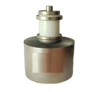
The RS3040CL is the air cooled triode that uses a coaxial design and metal-ceramic technology. It is designed for industrial generators upto 100MHz for applications like Dielectric heating, plastic welding & textile RF heating treatments. This triode can be used in continuous made as well as pulse mode. However for pulse mode the parameter depend on each equipment charascterstics.


| Technical specifications | |
|---|---|
| Filament | thoriated tungsten |
| Filament voltage | 8 V |
| Filament current | 185 A |
| Amplification factor | 20 |
| Inter-electrode Capacitance | |
| grid-cathode | 78pF |
| Grid to anode | 29pF |
| cathode-anode | 2pF |
| Maximum Ratings | |
|---|---|
| frenquency | 100 MHz |
| Anode voltage | 15 kV |
| Grid voltage | -1500 V |
| Peak cathode current | 45 A |
| Anode dissipation | 25 KW |
| Grid dissipation | 820 W |
| Cooling | |
|---|---|
| Air temperature at tube inlet | 25°C |
| Minimum Air flow cooling | 27 m³/min |
| Air Outlet temp. | 85°C |
| Max. Temp. at any point on the tube envelop | 220°C |
| Machanical | |
|---|---|
| Overall weight | 13 Kg |
| Overall diameter | 196 mm |
| Overall Length | 282.4 mm |
The tube must always be connected vertically. The base of the tube can be either up or down at the preference of the equipment manufacturer. The tube filament should be protected from shock and vibration.
The forced-air cooled tubes have radiator with finns that is fitted to the anode, through which the air is sucked. It is advisable that the air is drawn through the radiator fins, away from the filament and grid connections. The tubes can also be cooled with the air blown in through the base of the radiator and up past the filament connections. However this does suffer the disadvantage that hot air is blown onto the grid connection and into the equipment, which may cause overheating of other components. If the air is directed this way, it is recommended that the airflow be increased by approximately 20%.
The tube should be seated in an insulating duct and be protected from any vibration from the blower. This can be done by fitting a length of flexible ducting in the ducting to the tube. Please ensure appropriate air flow rate & pressure drop.
Whenever filament power is applied a coolant must be circulated through the anode water jacket even though no anode or grid voltages are present. 60% – 80% of the filament power appears as heat in the anode. In the absence of coolant flow the temperatures will rise to levels which are harmful for the tube. If the coolant flow is obstructed the coolant jacket may rupture from generated steam pressure.
Values shown for each type of service are based on the “absolute system” and are not to be exceeded under any service conditions. These ratings are limiting values outside which serviceability of the tube may be impaired. In order not to exceed absolute ratings the equipment designer has the responsibility of determining an average design value for each rating below the absolute value of that rating by a safety factor so that the absolute values will never be exceeded under any usual conditions of supply-voltage variation, load variation, or manufacturing variation in the equipment itself. It does not necessarily follow that combinations of absolute maximum ratings.
This tube is designed for commercial service, with no more than one normal off/on filament cycle per day. If additional cycling is anticipated we recommend the user to contact us for additional information.
With a new tube, or one that has been in storage for some period of time, operation with filament voltage only, at the nominal value of 8.0 volts, applied for a period of 30 to 60 minutes is recommended before full operation begins.
This allows the active getter material mounted within the filament structure to absorb any residual gas molecules which have accumulated during storage. Once normal operation has been established a minimum filament warm-up time of five seconds is normally sufficient.
At rated (nominal) filament voltage the peak emission capability of the tube is many times that needed for communications service. A reduction in filament voltage will lower the filament temperature, which will substantially increase life expectancy. The correct value of filament voltage should be determined for the particular application. It is recommended the tube be operated at full nominal voltage for an initial stabilization period of 100 to 200 hours before any action is taken to operate at reduced voltage. The voltage should gradually be reduced until there is a slight degradation in performance (such as power output or distortion). The voltage should then be increased a few tenths of a volt above the value where performance degradation was noted for operation. The operating point should be rechecked after 24 hours. Filament voltage should be closely regulated when voltage is to be reduced below nominal in this manner, to avoid any adverse influence by normal line voltage variations. Filament voltage should be measured at the tube base or socket, using an accurate rms-responding meter.
When cold, the resistance of a thoriated tungsten filament is very low, therefore the initial starting (inrush) current when filament voltage is applied can be many times the normal (hot) current; this can be detrimental to the longevity of a filament structure. Filament inrush current should never exceed a value of twice the nominal rated current. The use of a special impedance-limited filament transformer or other “step-start” circuitry in the supply side (primary) of the filament transformer is recommended.
Note. It is important that both anode and base cooling are required when the filament of the tube is operating, even though no other voltages are applied to the tube.
The maximum allowable grid dissipation for the triode is 820 Watts, determined approximately by the product of the dc grid current and the peak positive grid voltage. This value should not be exceeded except during tuning for very short periods. A grid over-current protection circuit with interlock set to trip-off above approx. 2.1 Ampere should be provided; the actual value of current used for the trip point depends on the value of anode current that occurs during normal operating conditions for a given application. In conventional cathode driven circuits, a protective spark-gap device should be connected between the dc cathode return and ground to help guard against excessive voltage that may exist under fault conditions.
In addition to normal cooling interlocks and anode and grid over-current interlocks, it is good practice to protect the tube from internal damage which could result from potential arcing at high anode voltage. In all cases some protective resistance, at least 5 Ohms, should be used in series with the tube’s anode supply to absorb power supply stored energy in case an arc should occur. An electronic crowbar, which will discharge power supply capacitors in a few microseconds after the start of an arc, may be required. The test for each electrode supply is to short each electrode to ground, one at a time, through a vacuum relay switch and a 6-inch length of #30 AGW copper wire. The wire will remain intact if protection is adequate.
The actual internal interelectrode capacitance of a tube is influenced by many variables in most applications, such as stray capacitance to the chassis, capacitance added by the socket used, stray capacitance between tube terminals, and wiring effects. To control the actual capacitance values within the tube, as the key component involved, the industry and the Military Services use a standard test procedure as described in Electronic Industries Association Standard RS-191. This requires the use of specially constructed test fixtures, which effectively shield all external tube leads from each other and eliminates any capacitance reading to “ground”. The test is performed on a cold tube in a special shielded fixture. Other factors being equal, controlling internal tube capacitance in this way normally assures good interchangeability of tubes over a period of time, even when the tube may be made by different manufacturers. The capacitance values shown in the manufacturer’s technical data, or test specifications, normally are taken in accordance with Standard RS-191.
The equipment designer is therefore cautioned to make allowance for the actual capacitance values which will exist in any normal application. Measurements should be taken with mounting which represents approximate final layout if capacitance values are highly significant in the design.
If tube is not installed in equipment then it should be stored in its own original shipping box, with original packing material. This will minimize the possibility of handling damage. Before storing a new tube please operate it in the equipment for 100-200 hours to ensure that it is not damaged and works properly. If the tube is still in store for 6 months then it is recommended to operate it in the equipment for 100-200 hours to ensure there has been no degradation in tube during storage. If tube operates satisfactory then it can be stored again.
Our electronic devices are safe to handle and operate, provided that the precautions stated are observed. We does not accept responsibility for damage or injury resulting from the use of electronic devices it produces. Equipment manufacturers and users must ensure that adequate precautions are taken. Appropriate warning labels and notices must be provided on equipments and in operating manuals. The operation of this triode valve may involve the following hazards.
High Voltage
The valve operates at voltages which can be deadly dangerous, and the equipment must be designed properly and operating precautions must be followed. Equipment must be designed so that no one can come in contact with high voltages. All equipment must include safety enclosures for high-voltage circuits and terminals, with interlock switches to open the primary circuits of the power supplies and to discharge high-voltage capacitors whenever access doors are opened. Interlock switches must not be bypassed or “cheated” to allow operation with access doors open. Always remember that HIGH VOLTAGE CAN KILL.
RF Radiations
Personnel must not be exposed to excessive RF radiation. A properly designed equipment cabinet with good RF electrical connection between panels will normally provide sufficient protection.
X-Ray Radiations
This device, when operating at voltages above 5 kV, produces progressively more dangerous X-rays as the voltage is increased; the radiation varies greatly during life. The device envelope provides only limited protection and further shielding may be required. A metal equipment cabinet with overlapping joints will usually provide sufficient shielding, but if there is any doubt an expert in this field should perform an X-ray survey of the equipment.
Hot Surface
Surface of tube can reach temperatures of several hundred deg. celcius and cause serious burns if touched for several minutes after all power is removed.

